How often have you needed to plug your iPod, iPad, iPhone, mp3 media player, portable radio, portable CD player, laptop computer, or any other device with a headphone output into an amplifier or mixer? It is not as simple as you may think. The headphone jack is typically a 1/8 inch (3.5 mm) stereo type with three contacts. Your amplifier/mixer console typically has an XLR type microphone input or 1/4 inch direct line input jack.
See updated information (Version 2) and reason for it follows below.
What you may be unaware of, is that as of this posting of this web page, an adapter cable does not exist off the shelf that will correctly send the audio from your source to the mixer/amplifier. Sure, there may be cables that look like they will work, but you will not be getting the proper signals you want. A typical example is the HOSA CMP-103. The literature claims it will sum the stereo output of an iPod or laptop to a mono console. This is only true if the output of you audio source is properly protected with limiting resistors to prevent shorting the outputs of the right and left channels together. If no limiting resistors are present, damage could occur to the output amplifiers or the sound could me marred, muddy or distorted.
If you go to your typical Radio Shack or audio specialty store and ask the sales droid that you need a cable to connect your ipod or other device to a mixer, his eyes will light up and say, "I got just what you need", and bring back a six foot cable with a 1/8 inch mono plug on one end and a 1/4 inch mono plug on the other. Although it may sound like it's working, this will not work properly! For a technical explanation of why this won't work click here. All you will get is the left channel audio and short out your right channel amplifier because of the mono sleeve on the 1/8 inch side as seen on the above link. This "may" work in your application as long as there is no important right channel content and the manufacturer of your iPod or such device was smart enough to put protective circuitry in the headphone output amplifier. The problem is, depending on your audio you are amplifying, there could be reverb, delay, panning, or surround info on the right channel which you will be missing. This could make for a strange sound out of just your amplified left channel.
One would ask, "why don't all output circuits have limiting resistors?". The limiting resistors will reduce the output level if you are using low impedance headphones or earbuds.
Typically you really don't need a "stereo" sound if you're just providing music or speech at your venue. You just want to amplify what your device is playing but in mono. That is, a mix of the left and right channels. So what's the problem?
It is the proper mixing of the two channels into one, technically called "summing" or adding together of both the left and right channels. This is usually accomplished with two resistors of equal value coming from the left and right channels and combining the audio into one channel for your amplifier.
Since no cable exists that I know of, I had to make my own. This involves some careful "close quarter" soldering so if you don't know how to solder, it is best to find a friend that can.
Version 1
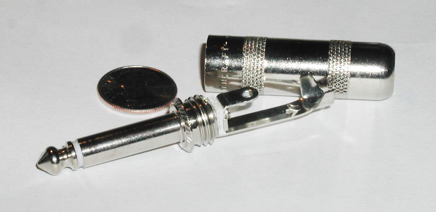
You will need a 1/8 inch stereo plug (available from Markertek.com p/n 35HDNNS $3.48),

1/4 inch mono plug (available from Markertek.com p/n SW280 $2.21),
a length (six to ten ft) of shielded mic cable, A few pieces of heat shrink tubing, two 1000 ohm 1/4 watt or 1/8 watt resistors,

and a lot of patience. If you don't have 1000 ohm 1/8th watt resistors, any value between 220 ohms and 1000 ohms should work without any damage. Just make adjustments in values to your test procedures shown below. Do not use any cheap foreign connectors. Use only Switchcraft or Neutrik brand connectors. It will be worth the added cost.
First prepare one end of the cable and solder the two conductors to the tip and ring of the 1/8 inch plug. Solder the shield to the sleeve of the connector.

Inspect your work and make sure there are no shorts. Use a piece (1-1/2 inch) of shrink tubing to cover your work an part of the cable.
Clear tubing is seen above.
Screw on the shell tightly and cover with a larger piece of shrink tubing.
(Another option to the above end is to purchase a 1/8 inch stereo patch cable, say 6 to 12 feet long, cut it in half and you have two 1/8 inch ends ready to go.)
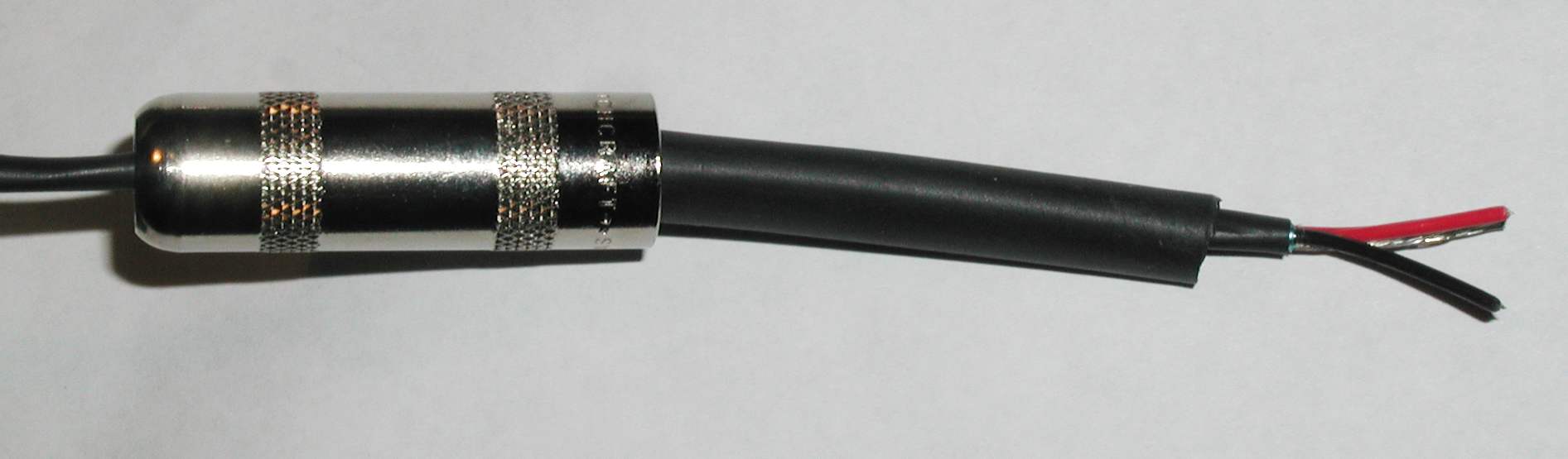
On the other end remove the 1/4 inch connector shell and immediately place on cable the correct direction. Place two pieces of 1/2 inch shrink tubing (1-1/2 inch long) on the cable end. The tubing acts as a strain relief to keep the cable from breaking and wearing at the critical points. Don't forget this step or you will have to cut the end off and start again.
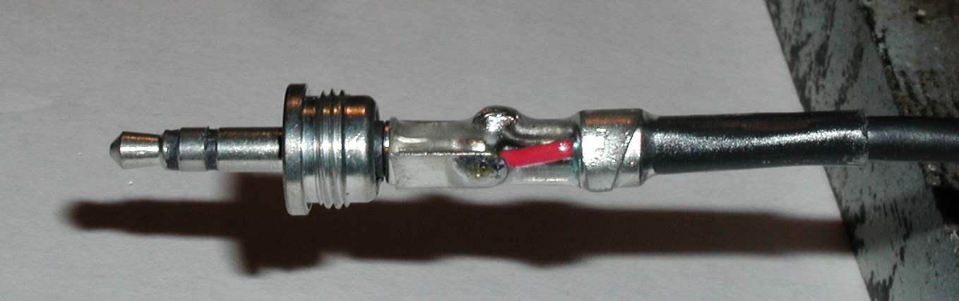
Prepare the end by exposing the two conductors. Solder the resistors on the two conductors and shrink tubing over the resistors.
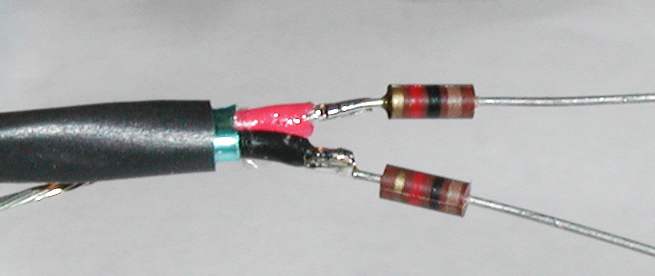
The 1/8 watt resistors will fit easily. If you use 1/4 watt resistors, it will be a very tight fit and you could crack the resistors. Tie the resistors together and carefully connect to center pin of 1/4 inch plug. Manipulate the shield and solder to the connector. Make sure everything will fit inside the 1/4 inch connector shell without shorting anything.
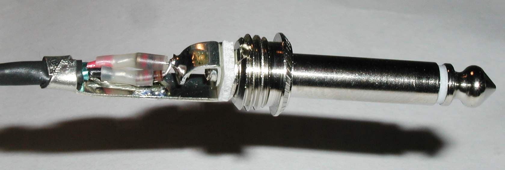
Place a piece of shrink tubing over all the work and part of the cable. Carefully screw the shell over the work. Place another piece of shrink over the shell. If all went well you should be done. Check your work by taking resistance measurements. 2000 ohms between the tip and ring of the 1/8 inch connector. On the 1/4 inch connector you should have 1000 ohms between the tip and the tip of the 1/8 inch connector. Also 1000 ohms from the same tip to the ring of the 1/8 inch connector. You should see zero ohms between the sleeves of both connectors, and infinite ohms between the tip and sleeve of both connectors. If you have anything other than these readings you must redo the whole 1/4 inch connector work.

Let me know if this has been helpful.
Update!
Version 2
I have been making dozens of these for sale recently but I had requests for a smaller 3.5 mm plug case/shell. Most iPhones and Android smartphones are protected with a case such as Otterbox or equivalent. The larger shell of the connector will not allow the plug to seat properly and you must remove the protective case in order to use it. This is usually not a problem with laptops or mp3 players. Smaller case/shell/housings are hard to find or too small to place summing resistors. I have researched and found a special cable with a 1/4 inch outside shell but it is sealed.

Part number 4200804 Barcode 040293998790
It has a fabric type jacket and is 3 feet long. You can cut it in half and make two 18 inch adapters or cut one plug off and have a 3 foot cable. These can be found on eBay for about US$5.00.
Instructions for making a Magic Cable follows:

Cut the cable to desired length and push fabric cover back but do not trim.

Strip inner plastic jacket back and twist shielded strands as shown.

Using temperature controlled soldering iron set at 700 degrees F, heat end
of two center leads to burn off insulation and tin with solder.

The tinned wires should look like this.

Trim 1000 ohm 1/8 watt resistors and tack solder them as shown.

Carefully heat shrink the tubing over the ends of resistors.

Cut portion of tab off 1/4 inch center tab. Crimp ground of connector around cable
insulation as shown.
Carefully solder ground to connector and resistors to center pin. Don't use too
much heat.

Cut a few pieces of 3/8 heatshrink tubing and shrink a few pieces to make a good
strain relief.

Thread shell on to plug. End result should look like this. Note: This particular
shell from Switchcraft
will fit over the 1/4 inch shell of the 1/8 inch (3.5 mm) plug. If not, you must place
shell and about 5 pieces of
shrink tubing on cable before soldering ground wire and resistors in the 1/4 inch plug.

The end result will look like the above picture.