This page demonstrates my experience with some of the Arduino systems. A lot has been written and posted to web pages both officially and unofficially, and on forums. Unfortunately much of the forum posts either don't address the problem correctly or post inaccurate or incomplete information. A lot of assumptions are made in configuring or interfacing to the Arduino system. This page will try to address just a few of the problems I have encountered and demonstrate how to get things working correctly. This page will address information on the official Arduino hardware and some of the Arduino clones available from Ebay and made in China.
I'm a late comer to the Arduino systems. In the past I have been involved in Microchip PIC processors. They are low cost, efficient, fast, and flexible. Recently I've noticed a surge in Arduino and Raspberry Pi, and all the many accessories available. Arduinos can be purchased from official Arduino suppliers or similar spin-offs (clones) on Ebay at a lower cost. You must watch out for some of the spin-offs. Some have different components or different configurations, but usually have the same pinouts as the Arduino factory versions, and work very similarly as long as the correct USB drivers are used.
Arduino has its origin in Italy. Almost all the software, development environment, libraries are available for free from the official Arduino site. There are many versions of the Arduino and are given Italian nicknames. Such as Uno, Yun, Nano, Leonardo, Duemilanove, Tre, Zero, Micro, Esplora, Mega, Robot, Pro, etc. These refer to the Atmel processor used and the on board features contained.
There are some new definitions you will encounter. The plug in accessories are called "shields". These are primarily sensors and I/O interfaces. Everything from WiFi, Ethernet, Barometer, Accelerometer, Thermometer, isolation relays, SD card interface, LED and LCD displays, real time clocks, USB interface, etc. The other term is "sketches". These refer to the source code you will write in the development software. The sketches are usually written in C++ language.
| Arduino's sample software and exclusive OEM boards should give you a functioning project right "out-of-the-box". However, once you use a third party processor board and/or accessory like an LCD display, you may encounter difficulties in getting it to work without correct drivers and/or changes to the code (sketch) or "includes". |
There are many help forums and pages dedicated to the Arduino project. Some on their official website and some unofficial help forums.
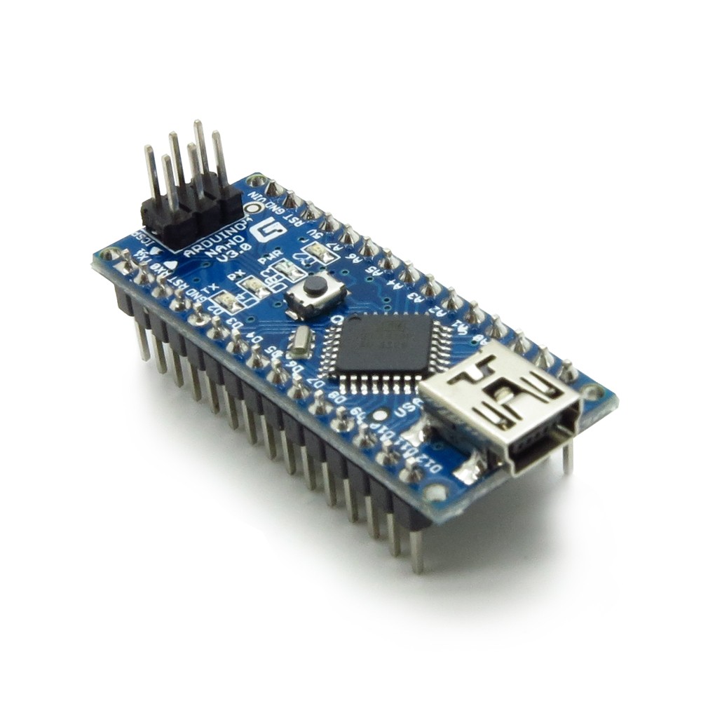
On this page I will explain and show my experiences with the Arduino Nano328 clone.
This is one of the smaller boards and can be purchased either from their official website or vendor, or on Ebay. A word of caution, most of the ones on Ebay are spin-offs and not exactly like the OEM versions but work similarly. The nice thing about the China spin-off boards is that they come preprogrammed with a bootloader and a light blinking program already uploaded to the board. This demonstrates the board is functioning right from the start.
Gotcha #1. One primary difference is the USB serial interface chip. The OEM (factory) version uses the Future Technology FTDI chip. The Arduino development software comes with the proper drivers for the FTDI chip. If you need more later drivers you can go directly to the Future Technology website to download them.
The Chinese spin-offs use the CH340G USB interface chip and requires you to download the correct drivers from Driverzone. Search for the ch341ser.zip file there or on Google. Download and unzip in a separate folder and use the driver installation program in your Operating System Device Drivers and find the USB com port settings to install the CH340 driver. As of this post the driver can be downloaded here from China. The file is also available from a Russian site but some computers with robust anti virus software will deny access to it. Once installed, and you plug an Arduino into you computers USB port it should it should recognize it immediately. If not, make sure the correct driver is installed. Check your computers device driver to make sure there are no yellow errors on the USB port. The comm port driver issue had me stumped for almost a week until I realized what the problem was and found the correct driver. Also the comm port number may change randomly so each time you connect your board to the USB port it may grab another unused port number.
Gotcha #2. You must use the correct library for your particular LCD display if it uses an I2C interface. You may be using a 20X4 display, or a 16X2 or other. You may need to contact the LCD vendor for the correct I2C address and configuration pins. Not all software and libraries will work with all displays. There are different versions of the LCD library such as the LiquidCrystal_I2C.h. The line in the sketch should look like this: #include <LiquidCrystal_I2C.h> Personally I would prefer a different name or version number for a "Library.h" if they are different from the original. This way there would be no confusion. If you buy your displays from a Chinese vendor from Ebay you may want to carefully look at the Ebay seller's page for links to correct "includes" or drivers specific to the display. You may need to contact the seller directly if information is not present.
I2C is the serial protocol used to communicate with multiple devices on the same two-wire buss. The typical library is Wire.h. The line in the sketch should look like this: #include <Wire.h>
Both these includes should be near the top. If you select the library from the Arduino development software it will automatically place it in the sketch.
| Note: You must remove any instances of an old library folder and all its contents before installing a new one. You can't just overwrite the outdated library. There are many supporting files in the specific library folder. There may be two locations of the library files. One should be in the Arduino program folder and another may be nested in your Documents and Settings under Arduino. If your compile errored out you should see a path to that Documents and Settings location. If you don't remove them all, when you install the new library through the Arduino development software, there may still be a compile error. Note: Be sure to close and restart the Arduino software for the library to take effect even after you install the library otherwise errors may still show on compiling. |
When you write the C++ code for your projects you will use "libraries" that hold routines such as your I2C and LCD so you don't have to rewrite them every time you create a new sketch. The Arduino development software comes with many libraries and proven sketch examples.
Gotcha #3. It took me awhile to figure out how to get the LCD display hooked up properly. Nowhere easily does it say you have to have pull-up resistors on the SDA (serial data) and SCL (serial clock) lines between the Nano and display. It looks like a value between 3K9 (3900 ohms) and 5K1 (5100 ohms) should be fine. Also there is no common address lines used for the SDA and SCL lines. It looks like most projects including Arduino demo sketches use A4 as the SDA and A5 as the SCL.
If you study and follow the examples exactly like I will show, your project will work right "out of the box". A few observations first. The Nano runs on 3.3 volts but is powered by one of four different ways. One is through the USB port, two is through the 5 volt pin marked 5V, and third is from the 12 volt pin marked Vin, and fourth is through an ICSP pin.
In order to facilitate ease of mounting or connections, you should solder header pins to both sides of the board. This way the whole board can be plugged into a socket or breadboard and removed if necessary. It is not recommended to solder wires directly to the Nano board.
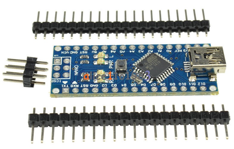
The above picture is what a Nano clone looks like from an Ebay Store I use a lot. You can purchase many of the shields, accessories, and breadboard wire from this store. Cut 15 pins from each header strip and solder them to the Nano board like the first picture on this page. It is not necessary to solder the ICSP pin header unless you plan on using it.
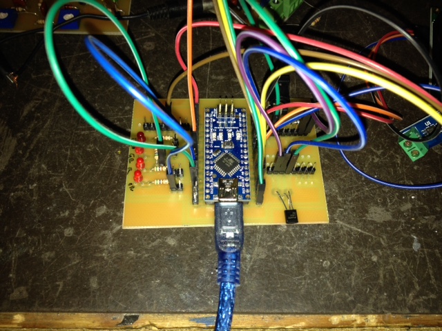
If you're heavy into prototyping, you may want to purchase or build a breakout board similar to the one I just made shown below. This board will allow you to interface led's, switches, power, and header connections to the outside world. Once I get the board the way I like it I will try to make it available to the public.
Where are my files (sketches)? Depending on your operating system they can be anywhere. With a normal XP system they are located in the c:\Documents and Settings\(yourusername)\Arduino\folderwithyoursketchname)\sketchname.ino
In order not to infringe on any copyrights I will only link to software and resources. Should a link become broken, email me and I will correct the problem.
©Copyright 2016 RickC