Audio circuits can be connected by way of two types. Balanced and unbalanced. Most consumer home gear uses unbalanced inputs and outputs. Semi-pro and professional gear usually utilize balanced inputs and outputs.
To complete any type of circuits, including audio circuits, you must have two wires (or signal paths). Signals flow from one piece of equipment to another via these two wires. Unbalanced is utilizing one active wire and one ground/shield wire return for a single audio feed. The audio is impressed on the one active or hot wire. Nearly all audio inputs require the active wire to be shielded. That is, the ground is braided or spirally wound around the active (hot) wire.
The following picture shows electrically, how unbalanced audio is passed from one piece of equipment to another:
As you can see, the audio output of Stage 1 is passed to the input of Stage 2 with the ground/shield as the return path. The term "return path" is commonly used to denote the completion of the circuit. You must complete a circuit in order for a circuit to function properly. Removing the ground will cause all kinds of hum and noise to be heard with almost no reproduction of the audio source.
In reality, the ground/shield has a small amount of resistance between both ends of the wire. Under the best of conditions, especially with short cables, this is not a problem. If you run unbalanced cables over 15 or so feet, and the two stages are being powered from separate AC receptacles, the cable resistance introduces annoying hum and/or buzz because the difference in grounds between the two units will have a signal that will be detected in the audio of the input stage. There is not much you can do except isolate the grounds, shorten the cable, and/or plug both power plugs in the same outlet strip. This is where balanced circuits excel. Balanced circuits can run hundreds of feet with no noticeable hum or buzz. A typical balanced circuit is shown below. Note: Your land telephone utilizes a balanced circuit. You will notice that if you have a line problem, you will hear a noticeable hum, clicking, or buzzing over the phone's receiver.
Balanced Audio Circuit
This is a typical transformer balanced audio circuit. As you will notice, special audio transformers isolate the audio from any part of the ground or chassis. The circuit on the left is the audio source (output) and the circuit on the right is an audio input. This eliminates the possibility of AC hum or buzz from being detected on the audio and is not referenced or is touching the chassis or ground at any point. The numbers in the above circuit are typical for standard XLR type connectors. In this example the source on the left would use an XLR male and the input circuit on the right would use an XLR female. In more modern equipment you may find active balanced "transformerless" circuits as shown below.
An active balanced circuit uses operational amplifier devices to provide a differential and isolated input and output as shown above. The two amplifying devices on the left provide a positive and negative output phase in reference to each other. The input amplifier on the right accepts the two phases with the summed output being the original source of audio. This method of canceling hum and interference is referred to as C.M.R. Common Mode Rejection. This means that the only thing the output stage on the right will present is only what the sum and difference of the source is providing from the left amplifier circuits regardless of ground loops or hum problems......in theory. If equipment is used in close proximity to each other and there is no huge ground differences or interference, this is more than suitable. If you are doing a remote sound job in a very noisy environment the CMR may not be enough to eliminate or cancel hum or interference. An isolation transformer may be needed to completely eliminate the AC hum.
Note: You can mix transformer or active balanced circuits on either inputs or outputs and have no degradation of quality.
Wire and connectors used in audio applications
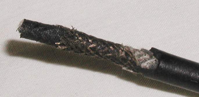
Above shows the braided ground surrounding a two conductor microphone cable. This
high quality cable is used in most professional applications. It has a rubber outside
jacket. Type: Belden 8413
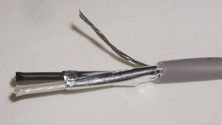
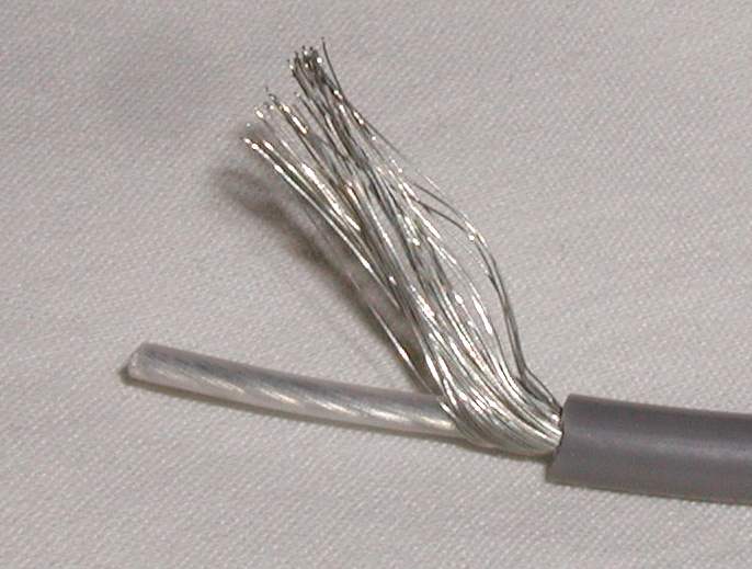
This cable has a foil shield and a stranded ground wire with vinyl outer jacket. This type of cable is
normally used to run permanent wiring in a studio. It is considered 100% shield.
Type: Belden 8451 or 9451
These do a good job eliminating noise, hum, RF, and buzz from getting into an audio input circuit.
If you look at the back of a stereo system, satellite receiver, amplifier or preamp, you will usually see RCA type connectors. These are unbalanced circuits.
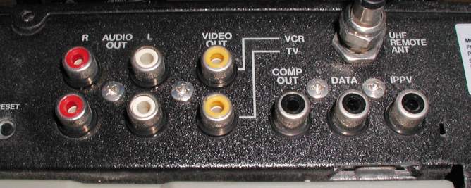
Some connectors are red, some black and some are yellow. Others are white. If you have red and white connectors, the red is the right channel and the white is the left channel.
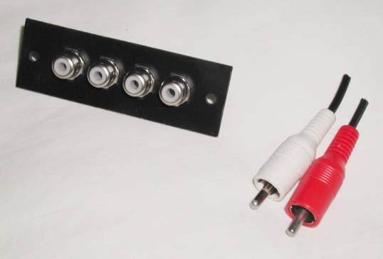
These are various RCA type connectors
If you have red and black, the red is the right channel and the black is the left channel. Any yellow is usually video inputs or outputs.
Unbalanced cables should not be used in lengths greater than 25 feet long otherwise you may have ground loop problems and you will loose some high frequencies due to the internal capacitance of the cable insulation.
Budget mic circuits look like this: *pic*
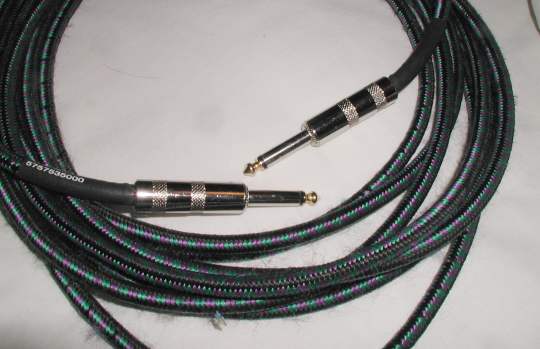
Guitar cables are made of high quality wire and look like the above. They are
1/4 inch unbalanced.
Guitar input circuits look like this:
*pic*
| Note: As a general rule, the Left Channel is typically Channel One or Channel A. The Right Channel is Channel Two or Channel B. |
Most headphones use 1/4 inch TRS plugs.
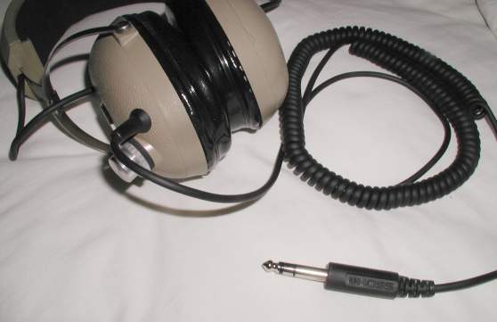
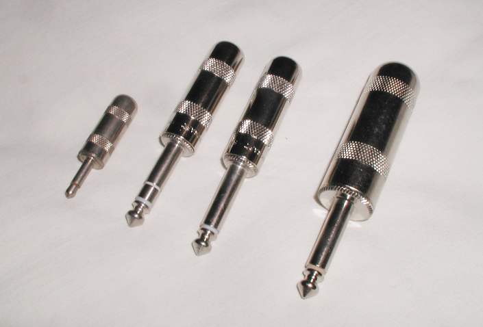
Above shows some high quality connectors.
The one on the far left is a 1/8 inch mono (2 circuit) plug (Switchcraft #0).
The second one over is a 1/4 inch stereo or balanced (3 circuit) plug (Switchcraft #290). Notice the tip, ring, and sleeve. It is sometimes referred to as a TRS conector. Notice the ring just behind the tip. This type of plug can be either stereo or balanced. Balanced will be explained in a further paragraph. If it is stereo, the tip is the left channel, the ring is the right channel, and the sleeve is ground/shield.
The third one over is a 1/4 inch mono (2 circuit) plug (Switchcraft #280). Just tip and sleeve (or ground).
The far right connector is the same as the previous but has a larger shell to accommodate larger wire such as speaker cables (Switchcraft #188).
Always try to stay with Switchcraft brand plugs. They are made to withstand heavy duty usage and are very reliable. However, sometimes they are hard to find. Stay away from imports. The solder tabs are thin, the strain reliefs are insufficient and the way they stamp the center pin to the solder tab is weak and will fail.
A lot of semi-pro and pro equipment uses 1/4 inch plugs and jacks.
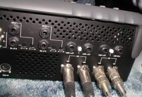
The back of this mixer has 1/4 inch balanced and unbalanced along with XLR mic
inputs
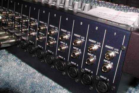
The back of Digidesign's 002 has XLR's and 1/4 inch balanced.
Some will use 1/8th inch TRS plugs. *pic*
You will see 1/8 inch usually on earphones (earbuds) like Sony Walkmans, Ipods, mp3 players, portable CD players, etc.
Usually 3-circuit plugs and jacks are used for balanced circuits.
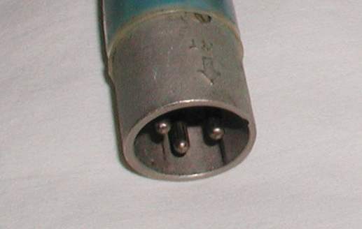
The following connectors are called XLR style microphone connectors. The one shown just below is a male type.
The one shown below is a female type.
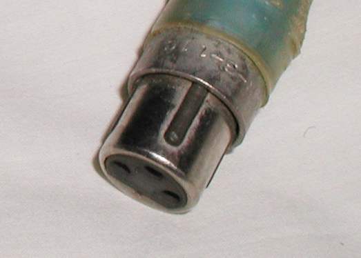
These connectors are usually used to connect a microphone to a mic preamp or mixer. They can also be used to connect two balanced pieces of equipment together. They are wired as balanced.
| Pin 3 | - Hot |
| Pin 2 | + Hot |
| Pin 1 | Gnd/Shield |
Be aware that the standard back in the late '70s had the two hot leads reversed. 3 was + and 2 was -. Make sure you understand this if using older gear where phase relationship is important.
|
A simple rule to follow: To understand which way the signal flows just remember, the pins point in the direction of the signal flow. That is, the female is the microphone amplifier input. The signal flows from the microphone male pins to the female XLR connector. The male has the signal source. The signal emanates from the male pins pointing outward towards the preamp input female sockets. |
©2007 Rick C.
Updated February17, 2007