Some of you own the MTR3 and MTR4(b) series of Mountain Topper QRP rigs, and probably the rest of their line of rigs from LNR Precision.
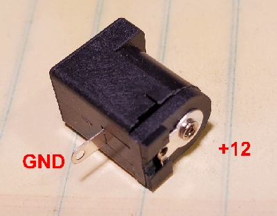
I was excited to receive mine and was anxious to try it out. I went to swap it out in my ham station with another QRP rig. I immediately found out my power plug would not fit into the MTR4 rig. It was an odd ball size. At least to me. Yes, they sent along a cable and they also sell pigtail cables online for about $13. It took me awhile to figure out what type of connector they used instead of the standard 5.5 x 2.1 mm that just about every other rig uses. After a bit of research I found out it was a 4.0 x 1.7 mm connector. What the..... Why? No one else uses it that I know.
Some will say to just make an adapter so you can use the standard 2.1 mm power connector but that's just one more thing to carry around and loose. Once lost, you're off the air.
I got inside my new MTR4b and had a look around. It looked pretty simple to just unsolder the factory one and install a "correct" one. Not so fast! The pinout of the factory one is nowhere like the new 5.5 x 2.1 mm receptacle I wanted to use. Still, I wasn't giving up that fast. I carefully unsoldered the factory one. You have to be careful not to pull the thru plating out of the holes. By the way, you'll most likely void any warranty but that was a risk I'd take.
This project is not for the faint of heart. You have to be precise in drilling your holes and making sure you don't let any static discharge ruin your rig.
I made a modification to my new connector by cutting off the back tab because it couldn't go through the board without a lot of surgery.
I took a #70 carbide drill bit and cut a slot into the circuit board shown below to accept the ground tab. Care was taken so the connector would just overhang the edge of the board like the factory connector and the slot wouldn't break the power trace going from the + pc hole to the power switch. I wasn't sure if the circuit board was multi layer and had traces running around the connectors but that was the chance I took.
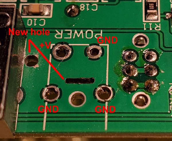
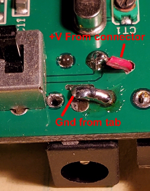
I also drilled a 1/16 hole next to the power switch as noted in picture above. After cleaning up any rosin left behind, I used some JB Weld® to glue the connector to the board. I soldered a piece of hookup wire to the back of the new connector, threaded it through the hole I drilled, and tacked it to the only + power pad shown below. I laid over the ground tab from the connector coming through the slot and soldered it to one of the three ground pads.
I had to open up the hole in the enclosure and offset it slightly to center the hole on the new connector. Use a "rat tail" round file.
After putting it together I powered it up and it works fine. Now all my QRP rigs all can use the standard 12 volt power supply.
Caveat: If using a wall wart that has a transformer in it, note that the unregulated voltage could be as high as 17 VDC (even though they are marked 12 VDC) which may be unstable for some rigs and could be deadly to the MTR rigs. The newer, smaller and cheaper switching supply wall warts will be closer to 12 volts but note that there may be switching noise that may appear in the receiver. The specifications for the MTR says 12 volts maximum and some forums state that you must not exceed 12.0 volts. I haven't seen the absolute maximum voltage but I wasn't going to take any chances so I replaced the red power wire with three 1N4001 diodes in series (cathodes towards the switch). This should drop the voltage by about 1.8 volts. This should be sufficient for most 13.8 volt power sources and since it should work to 6 volts according to specifications, the lowest voltage with three diodes should be 7.8 volts. Since most supplies are in the 12 volt range the three diodes should suffice. However if you were to plug straight into an auto cigarette lighter socket, you could see 14.8 volts or higher. You may need a few more diodes in series with the cigarette lighter cable.
Copyright ©2020 Rick C. Version 0.2 Jan 11, 2020