Detailing the K1FM Magnetic Loop Antenna
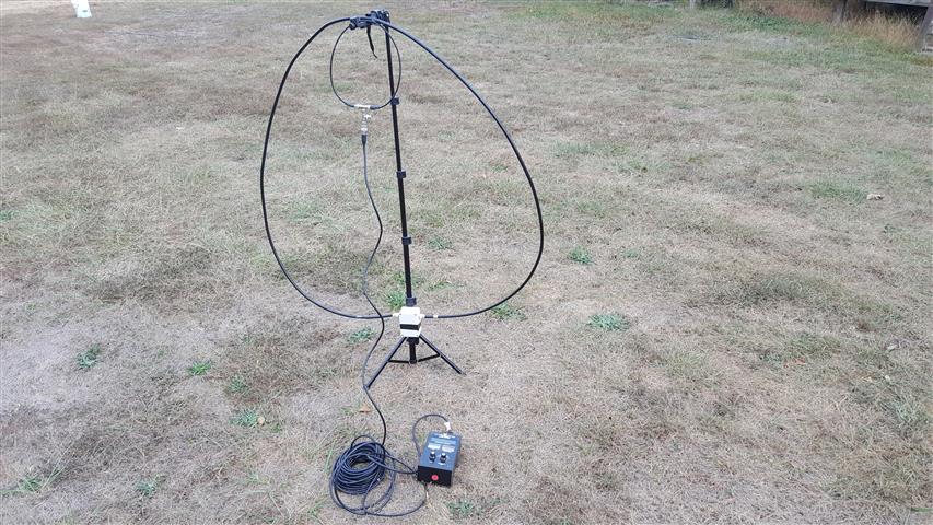
The summer of 2019 I was introduced to the K1FM HF Magnetic Loop Antenna. It was seen on the front cover of August 2018 QST magazine. An article in the May 2019 issue of QST featured this antenna by Alain De Carolis, K1FM, so I decided to build one from scratch. There were some things left out of the article and some items are hard or impossible to obtain. Mainly the geared tuning capacitor. Some detail as to the connections of the capacitor were vague. Nothing was mentioned that you cannot tune the whole HF band with only one loop unless you find a capacitor with a large tuning range. Obtaining the 3D printed parts takes a little bit of effort if you don't have a 3D printer or you've never ordered them online. If you have a friend that has a 3D printer you're all set. There is not much to the antenna. Just an exciter loop (smaller) and a radiator loop (larger). The radiator is just an LC tuned circuit.
The advantages of a magnetic loop antenna is its high efficiency, size, profile, low to ground mounting, ease of setting up, excellent for QRP, .... Its disadvantages are its narrow bandwidth, touchy tuning, fragile, partially waterproof, not wind proof, low power usage only unless you use a vacuum variable capacitor which will be much larger in size and cost more than the whole project. Also you must not stand or sit near the antenna when operating. You will be exposed to high levels of non-ionizing radiation .
The whole loop can be disassembled and carried in an old fabric type laptop case.
It's a great antenna for field day, contests, or setting up for emergency communications. It uses very little space, has a radiation pattern excellent for DX work. The radiation pattern is similar to a horizontal dipole with very sharp nulls on the broad sides. This can be an advantage if you are trying to null out an interfering signal.
With my first experience building this loop, I really needed to see what a schematic of it looked like. Here's the simple schematic:
I elected to position the tuning knob on the bottom of the enclosure when mounted to prevent water from getting into the enclosure if accidentally left out or caught in a rain storm.
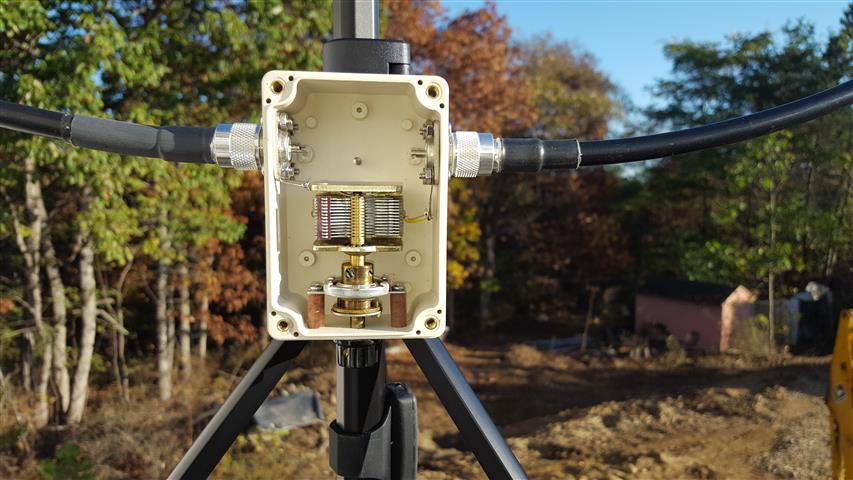
The above picture shows the fiber standoffs holding the tuning reduction gear in
place.
The capacitor is not screwed down. The back side of capacitor lies flat on the back
of the box and
the solder lugs hold it securely in place. As you can see the center pins of
SO239's aren't
connected to anything. SO239 flanges are on the inside of the box to provide
secure grounding, not just through the screws.
Use an MFJ259 or other antenna analyzer to trim cables.
The loop antenna system can be made almost waterproof. The BNC tee connections can be wrapped with plastic electrical tape. The PL259's can also be wrapped with tape. I haven't tried it but the connectors could be flooded with silicone grease to displace any moisture from getting into them. The SO239's can be caulked from the inside along with the 8 screws. The enclosure cover with this box has a rubber "O" ring in the cover. So light rain will be tolerated with the exception of water possibly detuning the loop. High wind could wreak havoc on loop though. It's not necessary but try to form the loops in a perfect circle. It might not make a difference in performance but it makes it look good. You can extend or retract the selfie mast to achieve a good circular form.
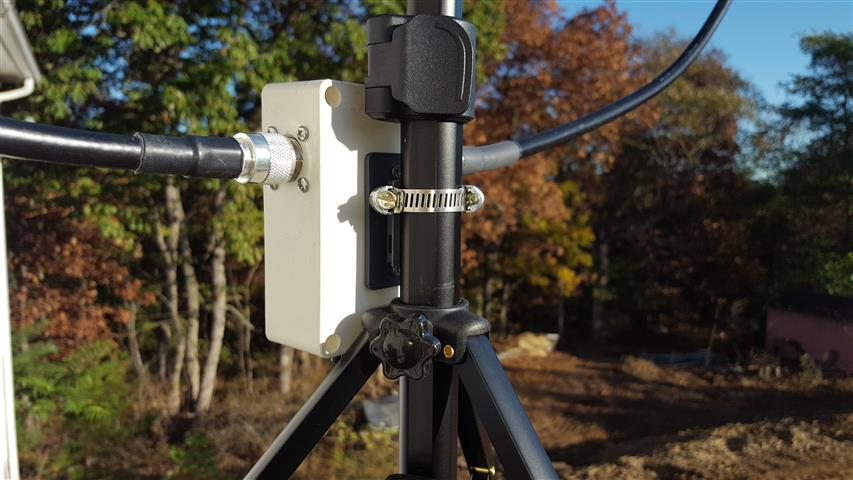
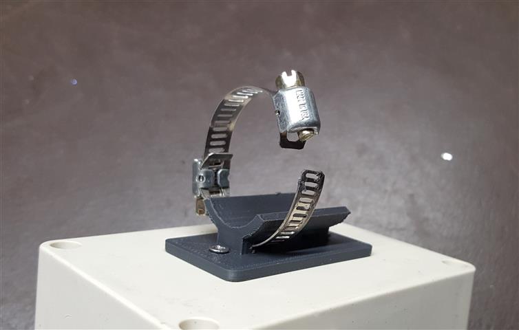
Using one clamp is sufficient to secure box to mast. There are two slots for
using tie wraps but having to
carry a bunch of ties and having to cut them off each time for disassembly is
not cost effective or convenient..
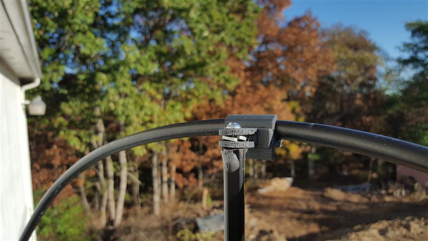
I took everything off the top of the selfie stick, JB Welded® #8 nuts inside end
of tube
and used an #8-32 screw with spacer washer to secure the 3D part.
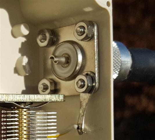
Detail of the SO239 mounting on both sides.
This is a list of the parts needed to build the loop: (Prices are all new, shop around for cheaper ones also.)
Hardware can be purchased at most hardware stores or stores like Lowe's and Home Depot..
125 inches LMR400 Coax $5 LMR cables are used because of the rigidness of the cable in order to keep its form. 125" for 40-30 meters.
25 inches LMR200 Coax $3 ebay
2 - LMR200 to BNC male crimp connectors $3 ebay
2 - LMR400 to PL259 crimp connectors per loop with adhesive heat shrink tubing $3 ebay
2 - SO239's flange mount $5 ebay
BNC Tee (all male) $3 ebay
Selfie tripod (Amazon.com) $21
2 - 3D parts $5 www.3dhub.com You can download the .stl's from the QST files section or contact me.
Enclosure (Amazon.com) ebay.com $7 Uxcell outdoor plastic industrial enclosure 98mm x 67mm x 50mm or Search Amazon and Ebay for "100x68x50 junction box" Sometimes US$5.00 and free shipping from China.
Capacitor (single gang 18 to 365 pf range) $6 ebay
Reduction tuning gear $19 (used) Search Google or eBay "Yaesu Jackson Brothers 6:1 Ratio Vernier Ball Reduction Drive Shaft FT101 Radio". They appear used from time to time on ebay. New ones are quite expensive. The one I referenced is made in the UK for Yaesu radios. Some of these gears come with a dial indicator that could be mounted in such a way you could use the pointer position to get you close to resonance.
Small tuning knob $1 ebay
2 - fiber or nylon standoffs and #4 screws to mount capacitor $0.50. If you
can't find them, try these links: https://www.kr4.us/standoff-nylon-34-10-pack.html,
https://www.digikey.com/product-detail/en/keystone-electronics/1903F/36-1903F-ND/61884,
as an example.
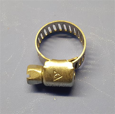
2 - 5/16 wide hose clamp (1/4 inch ID hose size) $2. The tie wraps can be used but you'll go through a lot of them setting up and tearing down all the time. Auto parts store.
8 - #4-40 x 1/2 stainless pan head screw $0.40 for SO 239
8 - #4-40 nut (large outline) $0.40 for SO 239
7 - #4 lock washer (internal tooth) $0.40 for SO 239
1 - #4 ground lug $0.15 for SO 239
2 - #4 self tapping Phillips screw stainless to mount 3D bracket to enclosure $0.18
8-32 x 1-1/4 screw, nuts, and washer for top 3D mounting clip.
25 ft or so RG174 with BNC's on each end to transceiver $12 ebay
Optional clear silicone caulk to keep moisture out of enclosure.
Special tools needed: Drill bits, stepped drill bit, and drill, coax crimper, heat gun, JB weld, SWR meter like the MFJ259
Operation: Never transmit into the loop until you are close to resonance or you may damage transmitter. First, listen to your desired frequency. Tune capacitor until you hear maximum noise or usable signal. It will be very touchy. Next you should have some sort of inline SWR indicator. Some are available from QRPGUYS.com. Another more cumbersome way is to carry around an MFJ259 or other antenna analyzer and dip your desired frequency. Don't QSY more than 10 khz either way without retuning!
Updated Jan 2, 2021 Rick C. Portions of this page are ©2021 Rick C.