I have been playing guitars for over 50 years. I have been repairing guitar electronics in recent years since opening an electronics repair shop. There are many configurations for electric guitar pickups. Some have from one to four pickups and some are paired together or wired in various configurations. Typically two pickups are normal. A pickup is a coil of wire wrapped around a magnetic core. It is placed under the strings. Location of the pickups from the bridge going to the neck gives a unique sound. If placed closer to the bridge, you get a thinner higher frequency sound. If pickup is mounted further up toward the neck, you get a fuller sound with richer lows. By selecting either pickup or a combination of both, you can get a different type of sound. Placing a third pickup gives even more variations of sound. Pickups may have individual or common volume and tone controls. A tone control varies or reduces the higher frequencies giving a more mellow sound. There can be individual volume controls for each pickup. There may also be a switch to select either pickup or both. With more than two pickups, switches can select all kinds of variations in tonal sounds. More variations can be made by reversing the phase of one pickup or shorting out one of the coils in a dual coil pickup.
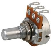
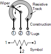
A "pot" is short for potentiometer or variable resistor such as a tone or volume control. A tone control reduces the higher frequencies going out to the guitar amplifier. A volume pot adjusts the amount of audio signal from the pickup to the guitar amplifier. The term wiper is the taper or tap that travels the distance of the resistor inside, varying the resistance between the wiper and the other two terminals of the pot and is shown as an arrow in the schematic.
Further information on potentiometers can be found here.
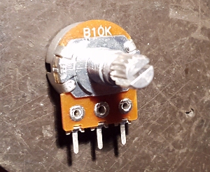
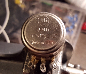
It is important that you know the difference between two major types of pots besides the resistance of the pot. It is called the taper or the linearity of the pot. This means the resistance tracks either in a linear or logarithmic range. In most audio applications you must use the logarithmic type pot rather than a linear type pot. Pots may have a reference designator written or stamped on the front or back of pot. It could be a letter "A" for audio or logarithmic and the letter "B" for linear pots. Other high quality military pots have other designations. A more detailed description can be seen here.
Some acoustical guitars have transducers and some have microphones mounted inside the sound hole. Others have a simple graphic equalizer built inside and even others have a tuner built in.
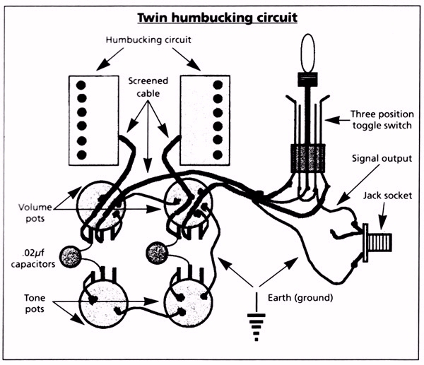
Humbucking: Back in 1935, designers noticed that hum from outside sources caused an annoying noise in an amplified guitar system so a solution was invented. Humbucking is a method of attempting to reduce stray 60 HZ hum from getting into the guitar electronics. It is accomplished by adding a second coil right next to the first coil but out of phase. In other words the second coil is wired backwards from the main coil. This attempt tries to cancel the stray EMF (Electro Magnetic Fields) caused by a nearby transformer or lighting system such as fluorescent light ballasts by subtracting the hum that appears simultaneously across both pickups. Of course this method is not perfect. Stray EMF can come from any and all directions so it's not perfect. Humbucking also slightly affects the tonal quality. Primarily the response at certain frequencies. This is why some guitars have a bypass switch so if there isn't any EMF nearby the second coil can be bypassed giving a cleaner sound.
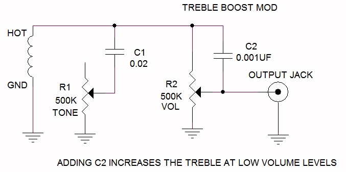
There are a lot of musicians that always want to get a unique or different or better sound by modifying their guitar by replacing the factory pickups with after market pickups. Some experiment by adding "boost" capacitors across the volume pots to enhance (or bleed) the rich higher frequencies at low levels as shown below. Others try reversing the phase or winding direction of one or more pickups, each giving another unique sound.
One simple mod you will see being sold is adding a capacitor across the volume pot as shown below as C2. The capacitor "boosts" the higher frequencies at lower levels.
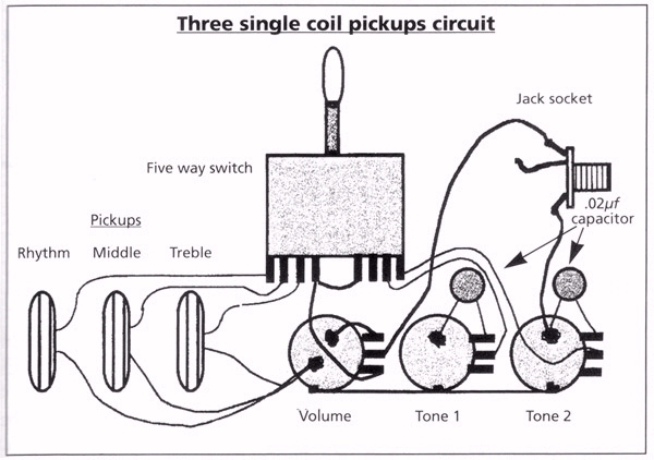
Instructions for modifications are usually graphical pictures with point to point wires and pictures of control pots showing how to modify the circuitry. These are wiring diagrams. These pictures do nothing for technicians to troubleshoot a problem. Looking at the circuit electrically what's called a schematic. Schematics are the electrical representation of the circuit and most technicians and engineers can understand and troubleshot the circuit better.
The picture below shows a simple schematic of a single pickup circuit.
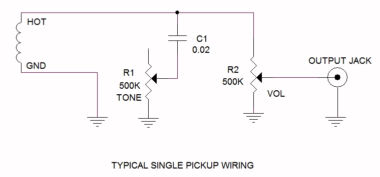
Most pickups are very high impedance (resistance) anywhere from 4,000 ohms to 8,000 ohms DC per pickup coil, so the tone and volume controls have to be relatively high in resistance usually 500K (500 thousand ohms) so as not to load the pickups. The tone capacitor is usually between 0.02uf to 0.05uf. Excessive shielding is required to keep hum from being heard in the guitar amplifier. Wires from the pickups are normally shielded. Ground wires are kept short and the case of the controls are all jumpered together with heavier ground wires. This reduces the possibility of hum being picked up. A good design is to also have any and all metal parts such as the bridge, pickup shells, strings and tailstock tied to ground. Other better guitars will have the whole pocket where the pots and switches lined with a copper shield. This will help with electrical interference but not magnetic fields but magnetic fields only affect the pickups.
More recently I've had to troubleshoot guitars only to find nothing wrong except the musician wore a belt mounted cellphone which emits enough radio frequency interference to cause all kinds of sputtering and scratching sound when the guitar was being held close to the waist.
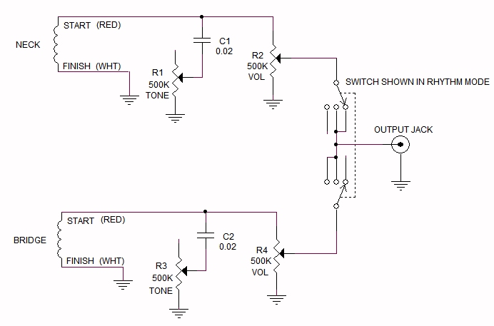
Many guitars have two pickups and a variation of one or two volume controls and/or one or two tone controls as shown below. Some with a selector switch or not. A caveat to this is that with the switch set to the center, or both pickups, and turning either pot down takes both pickups down. An explanation is shown in next paragraph.
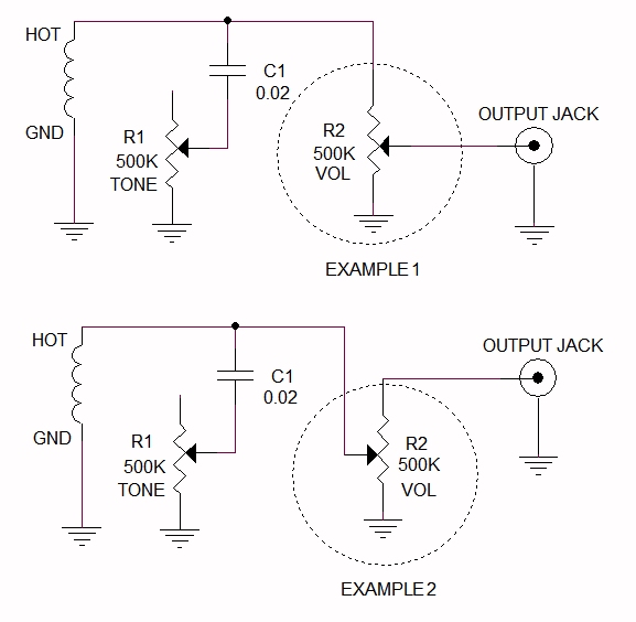
If you study the schematics shown above you may notice that the volume pot appears in two different ways. The above picture Example 1 has the wiper going to the output jack. In Example 2 the wiper goes toward the pickup. In each instance you will get almost the same sound. However in Example 2 with the volume control turned all the way down, the impedance (or resistance) on the center (hot) lead of the instrument cable is 500 thousand ohms to ground. This may cause a hum if the instrument cable is improperly shielded or there is some noise around the volume pot. In Example 1, the wiper approaches ground for lower volumes and thus shorts the center lead to ground preventing any stray noise going to the guitar amp. Of course this causes a problem when you have two or more pickups and volume controls wired using Example 1. Turning any one volume down will turn all pickups off. In this case Example 2 wiring should be used.
More modern electric and acoustic including bass guitars may have an active amplifier circuit which requires a battery. Sometimes a 9 volt and sometimes one or two AA size batteries. In most cases the battery is turned on when the instrument cable is plugged into the output jack from the guitar. If you aren't playing the guitar for awhile you must unplug the instrument cable from the guitar otherwise in a few weeks the battery will be dead. If you rehearse and perform about 4 hours a week you could get six months to a year of life out of a fresh battery. If you are a professional performer you should replace the battery every month or two regardless of battery condition. Some circuits will light up an LED light when battery is getting weak. If you don't have any indicator you can tell a battery is getting weak by a loss of volume or some distortion when playing clean.
Some examples of "wiring diagrams"
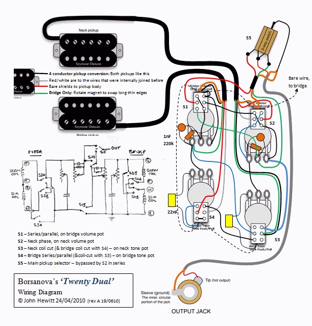
Below is a wiring diagram and a hand drawn schematic. To me, schematics make more sense and understanding.
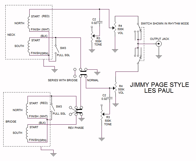
Below is an example where reversing the phase wiring changes the tonal quality.
Copyright ©2020 Rick C.
Ver 0.1 Nov 1, 2020