Standard bipolar silicon and germanium transistors and diodes can be easily tested in and out of circuit with a simple tool. A continuity tester using two AA penlight batteries and #222 bulb can be used for this test. Make sure that it uses two batteries and uses one incandescent bulb. This is because of the voltage drop properties of the semiconductor. An LED type or electronic buzzer type will not work properly. Of course the tester can be used to check operation of relays, continuity of cables and connectors, switches and fuses, etc. They are available from electrical supply houses, automotive parts stores and local hardware stores.
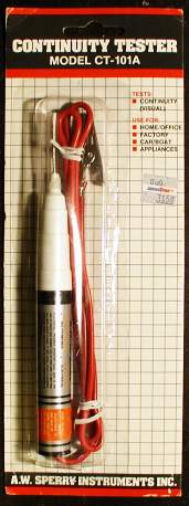
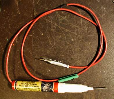
This is what a simple continuity tester looks like:
|
|
|
These can be purchased on line at Amazon.com or eBay for less than US$4.00: Search for Sperry CT-101A
In order to understand how to use the tester to test transistors, you will need to know how to test a diode first, and know what to look for. A diode is like a one-way electronic valve. Electrons flow only one way through the diode junction. When a source of more positive potential is applied to the anode, the diode will conduct. This is what is called "forward bias". If the diode is reversed, current will not pass through the diode. This is what is called "reverse bias". With that principal in mind, and using the circuit shown below, the tester light will illuminate.
Below is a picture of the tester illuminating with a diode forward biased. Notice the cathode (banded end) of the diode is in the alligator clip.
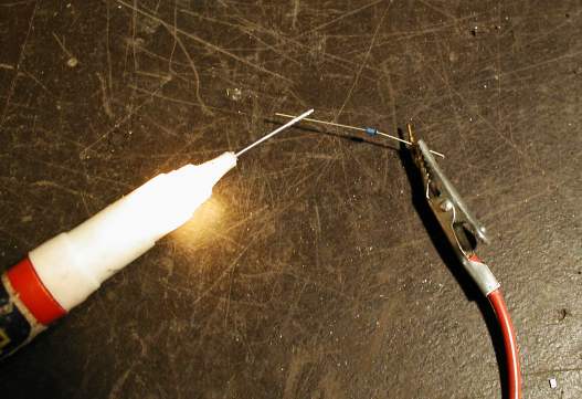
If you short the alligator clip to the probe tip you will see a brighter illumination than when connected to the diode. This is what is called an IR drop or a voltage drop across the diode junction. Note that silicon diodes have a forward voltage drop of about 0.7 volts. Germanium diodes may have a 0.3 volt drop. If you reverse the diode, the tester will not light. This is a good diode. If the light illuminates brightly both ways, or neither way, the diode is defective. Remember, it must light only in one direction. If the light illuminates very dimly on only one direction and not the other, the diode may still be okay. Usually a dim indication means the device could be a high frequency RF device.
It is important to use a fresh set of batteries when testing semiconductors because a weak set may not illuminate the tester properly and you might mis-diagnose a good transistor or diode. With that in mind, you can mentally match devices by observing the intensity of the tester light. Using a single cell tester or audible electronic continuity tester will give inconclusive results.
Below is a standard NPN bipolar transistor and a "diode representation" of the same transistor.
|
|
|
Test 1) If you hold the tip of the tester to the base and touch the emitter and then the collector, you should see the light illuminate like a diode. If either the emitter or collector or both lights brightly, the transistor is defective.
Test 2) Now place the alligator clip on the base. Touch the emitter and collector and you should not see any illumination. If you get a bright light on either the emitter or collector or both, the transistor is defective.
Test 3) Lastly, place the tester across the emitter and collector. You must not see the tester illuminate either way. If it passes the three tests, you can be sure the device is okay.
As you do more testing and get used to knowing what to look for, you can test transistors in-circuit. The above go-no go tests still hold true with the exception of the last test (Test 3) where you go across the emitter and collector. You may get an illumination in one direction because of other components in the circuit affecting your test. You may see an indication one direction and this may be okay. Usually Test 1 will tell if the transistor is 95% okay. In all my years, Test 1 has been successful in detecting a bad transistor. Remember that you must remove power from the circuit you are testing when doing the above procedures.
For testing PNP transistors simply remember to mentally reverse the diodes in your head and run the same tests. Below is what a PNP transistor looks like:
|
|
|
Enhancements
Replace the wire with rubber test lead wire for more flexibility.
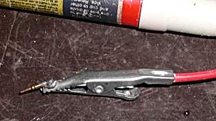
Solder a pin on the alligator clip for easier connector testing.
Please contact Rick for any questions or problems understanding this testing procedure.
©2012 Rick C.